The DSTW picks up speed
Modular structure
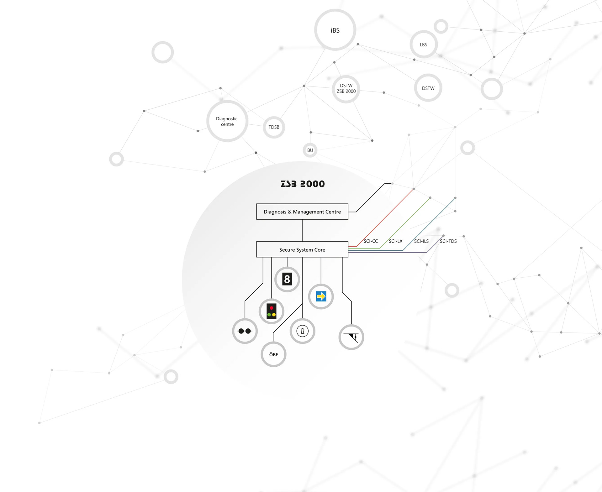
All our control and safety systems interact on a network basis. A cross-route network forms the basis for establishing any connections between the systems. Various protocols can be used for communication. These include conventional communication via STRENET (secure route network) and Dispo/Diag or communication via standardised interfaces (SCI), with which, for example, the control centre (SCI-CC), the interlockings (SCI-ILS) and level crossings (SCI-LX) are connected.

The modular network structure forms the basis for the integration of further systems and thus ensures the future viability of this architecture.
The independent axle counting system TDSB also communicates with the interlocking via the SCI-TDS interface.
ZSB 2000 – A Digital Signal Box of the First Hour
The railway has always been one of the safest means of transport. Railway signalling technology is of central importance for the reliable safety of the track. With over 150 years of experience, Scheidt & Bachmann is one of the most successful manufacturers in this field.
Railway and infrastructure operators in many countries rely on digital control and safety technology from Scheidt & Bachmann and operate their railways with ZSB2000 and BUES2000.
The (DSTW) ZSB 2000 digital interlocking with its super compact design offers everything needed for modern operations control. It is designed for use on main and branch lines both domestically and abroad. The system’s modular design enables flexible and cost-effective solutions. Thanks to the consistent use of state-of-the-art technologies and optimal adaptability to various customer requirements, cost-optimised solutions in terms of energy and life cycle have also become standard.
ETCS
New Paths with ETCS
Scheidt & Bachmann relies on a fully digital solution for all ETCS levels, in which information from the interlocking core is intelligently transmitted to the vehicle via a data link. In this way, road-specific information can be sent dynamically to the vehicle. The ETCS architecture from Scheidt & Bachmann provides for all levels and modes. The ETCS data can be sent via balises (level 1) or SCI-RBC (level 2/3). The solution is fully compliant with the UNISIG specification.
Our digital solution for Level 1 Full Supervision (FS) is already successfully in operation and in practice realises significant advantages over existing concepts. The same logic can also be used for Level 2/3. Data transmission is then realised via the Radio Block Centre (RBC).
Dynamic Level 1 FS offers various advantages for railway operations:
- Shorter travel times and increased performance
- Temporary speed restrictions can be dynamically controlled by the dispatcher
- Balises are saved (no repositioning, no throwing balises)
- No intermediate states due to lamp current measurement
- Central ETCS data storage in the interlocking
BCU (Balise Control Unit)
The BCU is an intelligent interface between the DSTW ZSB 2000 and the balise. The necessary ETCS information is transmitted from the interlocking to the BCU, which then generates the ETCS telegrams as required at runtime.
Signalling
The ‘Full Supervision’ ETCS mode is based on cab signalling. The driver receives all necessary information on the Driver Machine Interface (DMI). Fixed signals are thus obsolete, although these can be retained in a significantly simplified form as a fallback level and travel indicator. A complex signalling system is not necessary, so that the signals can be implemented much more cost-effectively with only two light points, for example.
Digitales ETCS Level 1 FS
oder auch L2 ohne Funk
Digitale Kommunikation mit dem Fahrzeug
- Direkte digitale Ansteuerung der Balisen vom Stellwerk via Balise Control Unit (BCU)
- Fahrstraßenscharfe Informationen werden an den Zug übertragen
- Kein Repositioning oder Wurfbalisen für Langsamfahrstellen notwendig
- Fahrdienstleiter kann Langsamfahrstellen in Bedienoberfläche einlegen
Digitale Kommunikation zur Balise
- Kein Abgriff/Messen des Signallampenstroms
- Deutliche Vereinfachung einer herkömmlichen LEU
- Keine Signale notwendig für Full Supervision
- Erhebliche Vereinfachung des Signalsystems und der Planung
ETCS Level 1 FS ohne Signale
- Für digitales ETCS Level 1 FS werden keine streckenseitigen Signale benötigt
- Ein vereinfachtes Signalsystem ist jedoch für Rangierfahrten und das Anzeigen einer gültigen MA sinnvoll
- Auch als Rückfallebene sind vereinfachte Signale sinnvoll
- Fahrtaufträge für Rangierfahrten oder Zugfahrten können aber prinzipiell auch über Funk (z. B. App auf Tablet/Smartphone) übertragen werden
Betrieb mit digitalem ETCS Level 1
- Reduktion von Fahrzeiten durch fahrstraßengenaue Profildaten
- Kürzere Blockabschnitte werden durch Wegfall der Vorsignale möglich
- Erhöhung der Kapazität (z. B. Hochleistungsblock)
- Verbesserung der Fahrplanstabilität (Verspätungsfortpflanzung)
Bahnübergänge und ETCS
- Einfache Einbindung von Bahnübergängen mit Packet 88
- Direkte Berücksichtigung bei der Definition der MA (MA bis zum BÜ)
Bahnübergänge und ETCS
- Einfache, geschwindigkeitsabhängige Einschaltung ➔ Übertragung einer bestimmten TSR für den vorgesehenen Zug (Zugnummer)
- Optimierter Betrieb bei BÜ-BÜ Ketten (heute muss bei Störung an jedem BÜ gehalten werden)
Life-Cycle-Costs
- Einfachere Wartung und Instandhaltung durch weniger Komponenten
- Zentrale Datenhaltung im Stellwerk, keine Änderungen vor Ort nötig
- Keine Wurfbalisen für Baustellen, da die Langsamfahrstelle (TSR) durch das Stellwerk eingelegt werden kann
- Keine komplexe Lampenstrommessung (keine Zwischenzustände)
Most modern control & operating technology
Control and Operating Technology
Integrated operating system (iBS)
The development of the integrated operating system (iBS) started with the ‘Design integrated operating station’ (DiB) project. Its aim is the manufacturer-independent operation of modern DSTW and ESTW via the standard interface SCI-CC. Compared to conventional operating systems, the iBS offers further significant advantages:
Attractive workplace:
- Ergonomic, standardised operating station with any monitor size
- Web-standard user interface
- Operation independent of the DSTW/ESTW type
Scalability
Due to our scalability concept, the iBS can be adapted to different requirements and network sizes. The smallest version is the iBScompact, which allows for easy accommodation. This can be upgraded to a full iBS at a later date.
Switching to any other operating location is also possible.
Cost optimisation and obsolescence concept:
- No safety requirement for the operator station (noSIL) due to process safeguarding
- Use of standard IT components (COTS)
- No proprietary, manufacturer-specific hardware
- Simplified approval procedure
Since it was piloted in 2020, the iBS integrated operating system iBS has now been successfully in operation on various routes in Germany.
Control and operating system (LBS)
For the regular operational management of a line, one or more dispatcher workstations are set up in the system concept of the DSTW ZSB 2000.
Signalling safety is established by approved procedures (ANSI/EISI). Safety-related requirements (SIL) are not imposed on the system (noSIL), so COTS (commercial off-the-shelf) components can be used.
Magnifying glass images and area overviews are not stored centrally but are automatically uploaded by the respective connected operating units. To ensure automatic operation, a ZSB 2000 line can be equipped with a train control system, in which case the traffic controller does not usually need to be involved.
This generic basic system enables the operation our digital interlocking technology with any user interfaces. In addition to the German the uniform EBO 2 user interface for Austria.
Local Operating Concept
In the ZSB 2000 digital interlocking, additional display and operating devices are used for special operating cases or for deviations from normal operation.
Local operating devices (ÖBE) can be used for on-site operation. Key buttons and operation on the dispatching and diagnostic system are also possible.
Local operating interface
A local display and operation can be provided for maintenance and servicing. The function of this device is limited exclusively to the operating range of the associated ZSB 2000 system and allows the request of routes and shunting routes. Auxiliary actions with safety responsibility can also be carried out by this device. It is combined with the existing diagnostic system.
User interface
Depending on the customer‘s requirements, the magnifier image belonging to the station can be switched on and operated on the station computer. The operating options and the procedure depend on the respective display and operating system of the customer (e.g. EBO2).
Key lock
In certain applications, such as AWANST or mechanical turnouts, a key lock can be installed at the corresponding points (e.g. turnout). After release by the operator, the operating personnel can set the travel path on site via mechanical key dependencies. Integration for the operation of mechanical barrier systems is also possible.
Integrated Control System (iBS)
As a part of DB Netz AG‘s new system architecture in the area of the control and signalling equipment (LST), Scheidt & Bachmann has developed the integrated control system (iBS). It enables the manufacturer-independent operation of modern DSTW and ESTW via the standard interface SCI-CC. The integrated control system does not contain any safety-related functions and integrates all applications required for the DB driveway service in a uniform look & feel.
PSB 2000
Intelligent Platform Concept
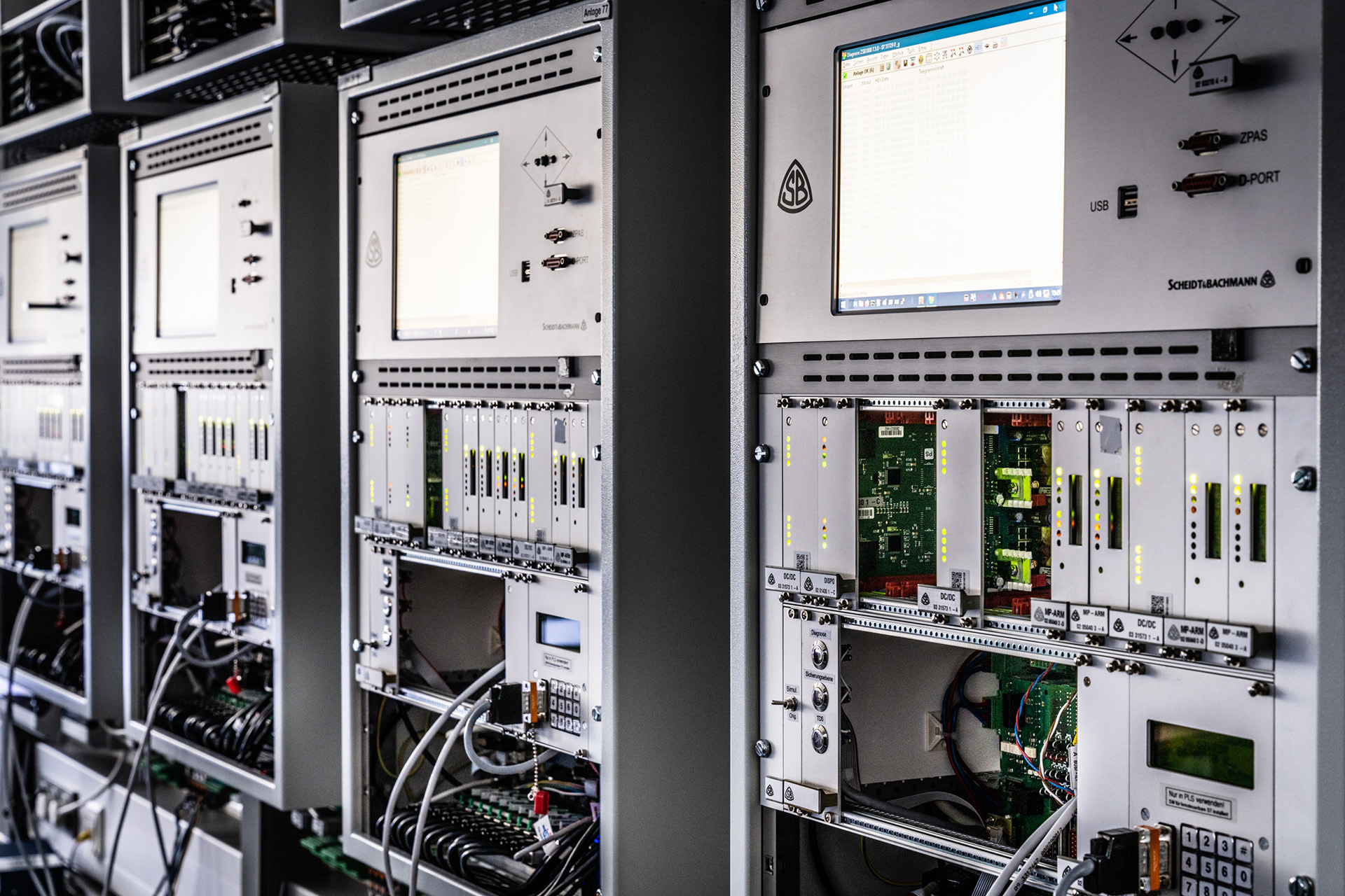
Ever since we began to develop digitalised control and safety technology, we have pursued a modern and flexible platform strategy. The Scheidt & Bachmann platform (PSB 2000) has been continuously developed since then and forms the basis for our BUES 2000 level crossing and the ZSB 2000 interlocking. It follows the concept of distributed intelligence and allows functions and hardware to be decoupled from each other and thus to react individually to the most diverse customer requirements.
The platform, consisting of:
- the hardware modules
- the associated firmware
- the operating systems and
- the generic basic software components,
is always identical and is used both for the BUES 2000 level crossing technology and for the DSTW ZSB 2000.
This common platform results in cost-optimising synergy effects, which help to simplify development, approval, production and spare parts supply. The same spare parts can be kept in stock for the maintenance of the DSTW ZSB 2000 and for the BUES 2000 level crossing technology. Thus, the amount of necessary spare parts is reduced, and maintenance staff can easily be trained on two very similar technologies.
The necessary and often very different functions and requirements of the markets are achieved by projecting the generic software. Thanks to the platform strategy, we are optimally equipped for the implementation of different market-specific requirements.
Minimise Operating Costs
During the development stage of the DSTW ZSB 2000, special emphasis was already placed on the use of modern and energy-saving technologies. For this reason, too, the separation of energy and information was consistently implemented in the control principle of the field elements.
For example, only LED signal heads were used right from the start, with the light point control being self-intelligent. The entire hardware of the DSTW ZSB 2000 was designed in such a way that it can be used without additional heating or air-conditioning equipment. The interlocking core itself has been optimised so that power consumption of less than 100 W is the norm. This means that the total power of a station (for example, a simple crossing station) with indoor and outdoor equipment is less than 0.4 kW.
Life Cycle Cost – Optimised and Sustainable
For economic operational management, railway and infrastructure operators not only need low investment costs but also systems with optimized and sustainable life cycle costs. With this in mind, the question of the ability to supply spare parts (obsolescence) in order to achieve the expected service life of interlocking and level crossing systems has become an important issue in recent years, especially for digital systems in control and safety technology.
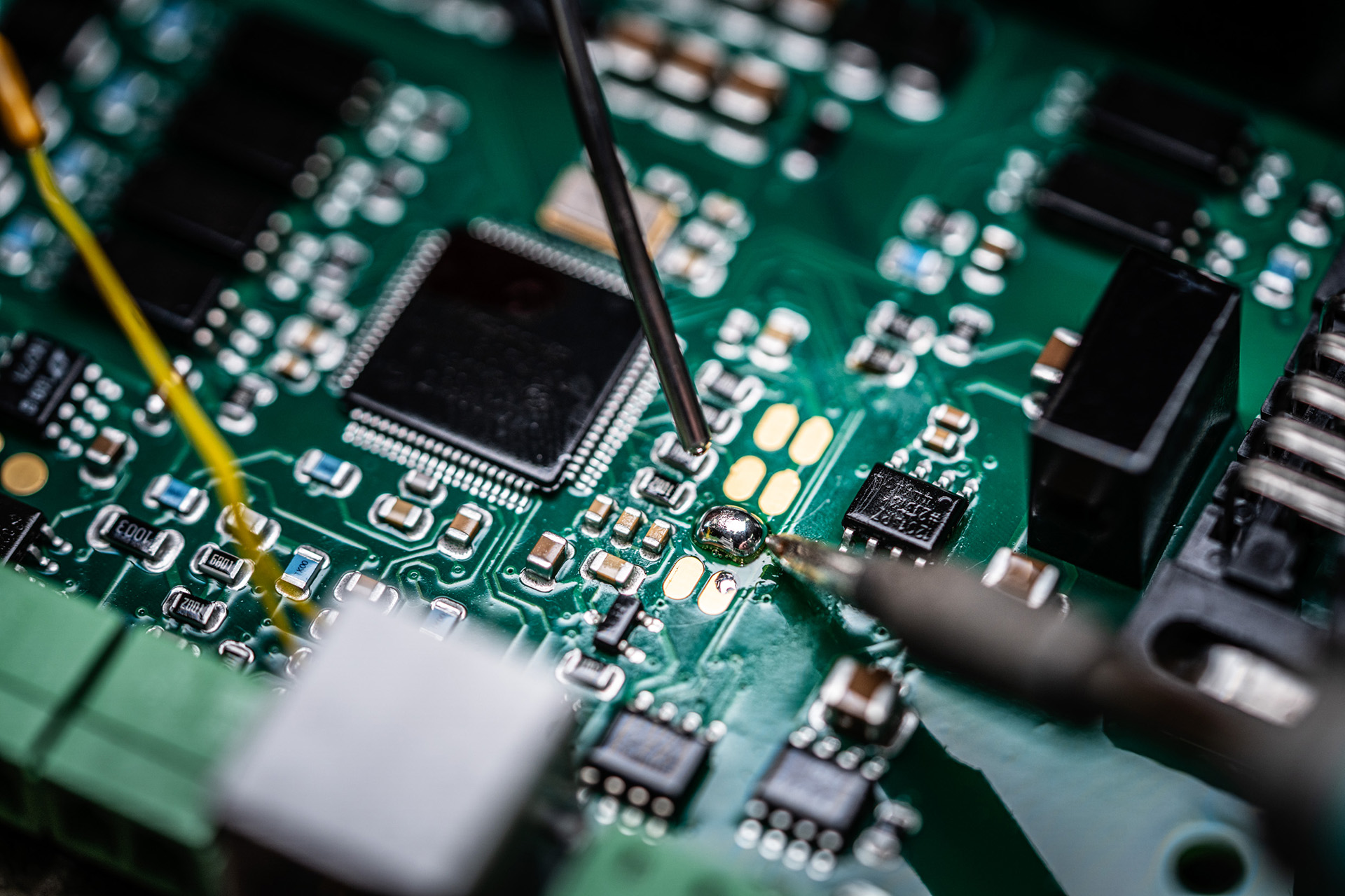
For technically safe components, we offer long-term backwards compatibility of our assemblies. Here, the constantly growing performance of digital components makes it possible to integrate future function extensions without any problems and to enable a pin-compatible replacement of old modules.
In order to be able to realise these two aspects, corresponding strategic framework conditions were already introduced in the basic design. The system architecture of the ZSB 2000 and BUES 2000 technology is based on a uniform platform strategy. With a strict separation of hardware and software, backwards-compatible and technologically permanently further developed modules ensure constant functional extensions and long-term operability.
For this purpose, we use the tools widely used in the semiconductor technology market. One of these is the FPGA (Field Programmable Gate Array), with the help of which the essential and critical components of our technology can be ’self-produced’ via self-programming. Delivery issues caused by component discontinuations can thus be specifically and permanently prevented. The approved system software can therefore be used and expanded in the long term.
The new PSB 2000 Help
Modern Service Concept
Each operating point of the DSTW ZSB 2000 has a diagnostic module which is connected to the safe system core via a non-reactive interface. The diagnostic data received via this interface can optionally be displayed via a graphic or text-based interface and made available for remote access.
Local diagnosis
A diagnostic software is installed on the local PC of the respective operating point. This software processes the data received from the ZSB 2000 and makes it available to the service and maintenance personnel. The diagnostic computer is also used in the same way in other Scheidt & Bachmann systems.
Diagnostic interface
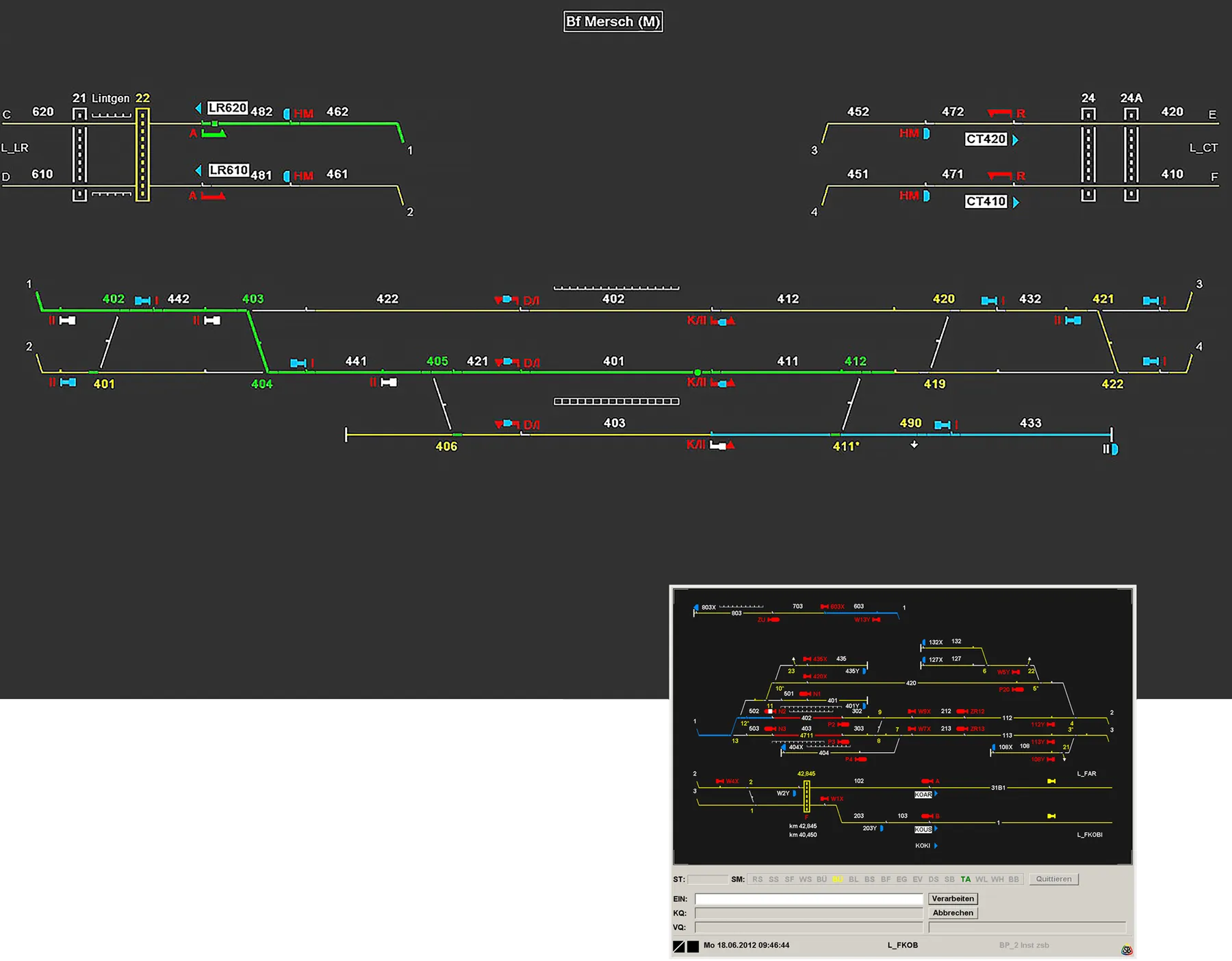
The graphic interface of the diagnostic system provides an overview of the states of all subsystems of the operating point in an overview screen for the maintenance personnel. In addition to displaying active status changes of external elements, faulty elements are also visualised clearly and in real time. Further diagnostic information can be called up via the menu and analysed by means of online help or additional evaluation tools.
Data exchange
In our networked world, it is of great importance that data are always available where they are needed. The diagnostic system of the ZSB 2000 units forms the basis for this. The diagnostic computer can forward the determined diagnostic data via a wide variety of transmission paths. In addition to leased-line-based data transmission via copper or fibre-optic connections, a wide variety of digital transmission paths such as the internet, telephone and mobile phone networks can be used. The transmitted diagnostic data can be retrieved as a website regardless of location.
Signaling with LED technology
Signalling with intelligent LED technology
In the DSTW ZSB 2000, self-intelligent LED signal heads are used, which are controlled safely in terms of signalling technology. The signal aspects are controlled via a safe digital module, the LSS-BG (light signal control module), which is installed at each main signal location.
LSS assembly
The LSS-BG is the interface between the safety level and the external signalling or train control. It commands the signal aspects and controls the PZB and ETCS balises (BCU).
LED universal matrix indicator
On the matrix indicator, which is available in yellow and white, every sign that can be displayed with the matrix can be controlled and monitored via software configuration.
LED signal heads
The LED signal heads are designed as 200 mm / 100 mm and 80 mm LED optics. Each signal head consists of a large number of individual LEDs that are connected in chains and monitored. All signal heads have their own intelligence and digital communication interfaces. This enables modern control and permanent automatic failure monitoring.
Track sensors
Intelligence for Track Vacancy Detection
The Scheidt & Bachmann axle counting system is thousandfold in Europe and guarantees safe railway operation. It is deployed in the DSTW ZSB 2000 and in the BUES 2000 level crossing protection system.
The axle counting system evaluates the number of detected axles and their direction. The clearance information determined from this is transmitted to the higher-level system.
For very compact applications, the axle counting system can be an integral part of the ZSB 2000 fuse level. It can also be designed as a separate system, which then communicates with the interlocking logic via the standard SCI-TDS interface.
Axle sensor evaluation module
The axle sensor evaluation module evaluates the inductive damping of the axle sensor by the wheel rim and digitally transmits each detected axle with the corresponding direction to the higher-level system.
Axle sensor
The axle sensor consists of two inductive loops built into a compact, impact-resistant and waterproof plastic housing. The component is clamped to the rail with a universal fastening and can be mounted and dismounted very easily.
Feedback
The system consisting of axle sensor and evaluation module can also be used as a feedback signal. The feedback signal is output as a galvanically free contact for any application. Extensive configuration options are available for direction, output delay, output duration, etc. A digital connection to a higher-level control system is possible but not necessary.

Your direct contact:
Dominik Oyen
Tel. +49 172 2063982
oyen.dominik@scheidt-bachmann.de

Frank Dohmen
Human Resources

Yvonne Kuzmanovic
Human Resources
Scheidt & Bachmann GmbH
Breite Str. 132
41238 Mönchengladbach